4+1 Architectural View Model
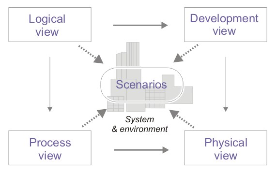
Logical View
- Describes the system's functionality from the user's perspective.
- Captures abstract data types and their relationships.
- Typically represented using a UML Class diagram.
Development View
- Offers a detailed insight into the system from a programmer's vantage.
- Addresses the module organization, source code structure, and software architecture.
- Represented using a UML Package diagram.
Physical View
- Concerns the physical hardware and topology on which the system operates.
- Provides a system engineer's perspective on system topology and distribution.
- Illustrated through a UML Deployment diagram.
Scenarios
- Depicts sequences of interactions among objects and processes.
- Demonstrates how various system elements collaborate to execute specific functionalities.
- Illustrated with UML Use Case diagrams.
Process View
- Focuses on the dynamic behavior and concurrency of the system.
- Emphasizes the system's run-time behavior.
- Commonly illustrated using a UML Sequence diagram.
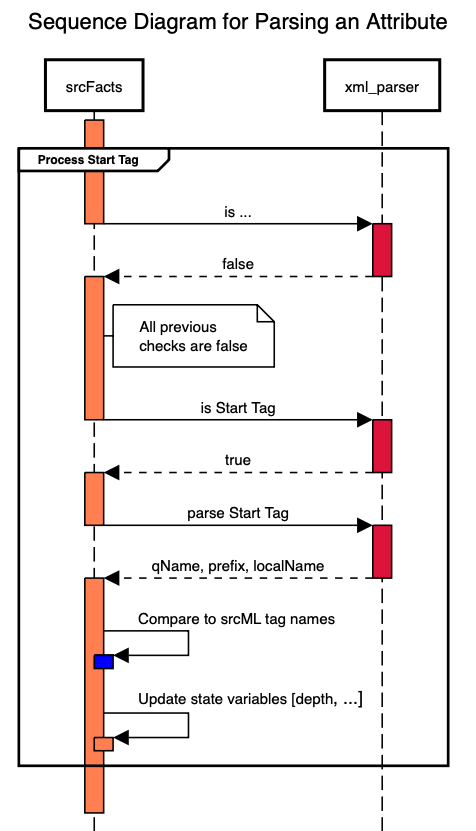
UML Sequence Diagrams
- Depicts sequences of interactions among objects and processes.
- Demonstrates how various system elements collaborate to execute specific functionalities.
- Illustrated with UML Use Case diagrams.
UML Sequence Diagrams
- Objective: Primarily captures the flow of messages (like method calls and return messages) between different objects over time.
- Lifelines: Represent objects or actors. Displayed as dashed vertical lines.
- Messages: Represent interactions between lifelines. Displayed as arrows between these lifelines.
- Activation bars: Depict the period an object is active or in control.
- Time Sequence: The vertical space represents time. Events are read from top to bottom, illustrating the sequence of interactions.
Benefits:
- Offers clarity about the order of object interactions
- Provides a concise view of system dynamics and object roles during specific scenarios
- Facilitates debugging by visualizing the expected system behavior.
- User-friendliness: Should have an intuitive interface
- Feature set: Should support advanced UML constructs and customizations
- Collaboration capabilities: Enables team-based designing
- Integration: Ability to integrate with other tools, platforms, or version control systems
- Export/Import: Provides multiple export/import options for various formats and resolutions
- Draw.io (or diagrams.net)
- Lucidchart
- Microsoft Visio
- StarUML
- PlantUML (text-based)
- sequencediagram.org
Sequence Diagram: Objects
Sequence Diagram: Call
Sequence Diagram: Request/Response
Sequence Diagram: Activation
Drawing Language